| |
Dragon Pz.Kpfw.IV
Ausf.E "3-in-1" (6264)
by Frank De Sisto
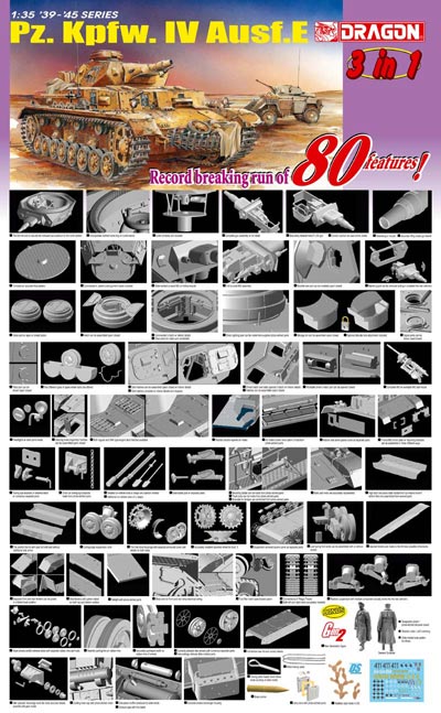
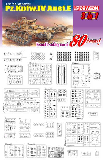
1/35-scale styrene/multimedia kit. Contains: 633 styrene plastic parts
(including 23 clear and 23 for one “Gen2” figure), two bags
of “handed” styrene “Magic Tracks”, three photo-etched
brass frets, three DS-100 parts, one turned aluminum and two turned brass
parts, four formed brass parts, ten formed wire parts, one piece of metal
cable, ten decal marking schemes and ten pages of instructions in 18 steps.
It is very difficult not to get excited about this kit. Because, despite
the updates on the DML web site and the occasional update on this site
by Tom Cockle (which can erode the “surprise” factor somewhat),
once I held the parts in my hands, I knew for certain that this kit is
simply stunning. For those of us who thought (and rightly so, in my opinion)
that the DML Tiger Is and the 8.8cm FlaK36 were “something else”,
this kit is clearly a step above even them.
One of the things that struck me was the attention to details in places
that will not be readily visible when the model is completely assembled.
For instance, the underside of the turret is not simply a flat plate with
a big circular hole in it and a pair of tabs to keep it in place on the
hull roof. It is detailed and includes a toothed ring, which in reality
would engage the turret traverse gear-box mechanism (which is also included).
The entire assembly is then attached to the hull floor by the turret basket
floor much like the prototype (more on the turret’s interior later).
In another departure, the undersides of both sets of fenders (that’s
correct, two sets, but more on them later) are not moonscapes of knock-out
pin marks. Instead, they are completely detailed with framing, bolt heads
and the “reverse side” of the non-skid pattern seen on the
top surfaces. And, there’s not a pin mark in sight. There is detail
behind the final drive assemblies that will be hidden after assembly,
but which will be useful if depicting the panzer undergoing maintenance,
or in a destroyed configuration. Another small point is the fuel filler
caps as seen on the hull side. They are separate and can be shown open.
Rather conventional, right? What’s notable here is that DML also
provides properly-shaped fairings (with pipe detail) over the openings,
on the inside of the hull.
The turret interior is nearly all there, except for the small storage
boxes, the fume extractor fan, some fittings and conduits, etc. The gun
breech for the 7.5cm KwK is very nicely done and is not simply “blocks
and tubes”. It boasts a separate sliding breech block, telescopic
sight, co-axial MG34 and mount, recoil guard, internal mounts and spent
shell bag. To this can be mounted either a plastic gun tube (with rifling
at the bore) or a turned aluminum gun tube. All of the view-ports can
be shown opened or closed and have clear inserts as well as hinge details.
The commander’s cupola also has interior details including clear
parts for the vision blocks. There is a multi-part traverse mechanism
(including gear-box and hand-wheels) for the gunner as well as seats for
all three turret crew members. Finally, the circular floor plate is attached
with various frames and has a non-skid pattern. The only other interior
details consist of a very nicely rendered radio operator’s MG34,
which is complete with inner mounting plate, sight, head pad and grips.
There is an ammunition bag given but it is not mentioned in the instructions.
This kind of treatment of the interior is risky on DML’s part because
despite what they have given in this area, some modelers may be critical
because they may feel the designers should have gone further.
All hatches are separate including the two types of engine deck doors
(standard and “Tropen”, with the latter featuring etched brass
details for their insides), cupola split-hatch (and split view-port covers),
radio operator and driver’s hatch (featuring separate signal-port
flaps) and the final drive access hatches. Curiously, the main transmission
access hatch is molded in place. All hull view-ports are separate and
feature clear parts for the vision blocks. The driver’s visor is
movable, but there is no clear part for the glass block, which is rather
curious considering the extensive use of such things elsewhere. The main
hull rear plate also features a separate access plate as well as a filler
port cover. The turret has separate side doors, side and front view-ports
and a separate signal-port flap. Incidentally, there are no knock-out
pin marks on any surfaces of these hatches. Another nice touch is tiny
photo-etched tear-drop-shaped covers for the key-holes for many of the
hatches, which can be positioned any way the modeler chooses.
There are two different lower hull pans, one with and one without appliqué
armor panels. Either features complete access plate and bolt details on
the belly. To either one is added the separate front and rear panels,
with the rear panel featuring, for the first time, the proper bolt details
on the separate strip that connected the superstructure to the hull (and
which allowed for the complete removal of the engine deck in the field).
There are two sets of fenders. One has locating holes for the set o
f tools
that contains molded-on clamps. The second set of fenders have no locating
holes and are to be used if the modeler chooses the second tool set (with
no molded-on clamps) and its accompanying photo-etched clamps and brackets.
To either fender set is added separate front and rear mud flaps, as well
as other details, such as a properly-depicted inner section as seen where
the fender attached to the glacis plate.
The suspension system includes fully articulated bogie spring mounts
(including variations in some of the fittings), separate fairings for
the mounting brackets, separate bump-stops and crisply molded return roller
mounts. The road wheels themselves are each multi-part assemblies, featuring
a wheel rim, hub and tire. The hard styrene tires have a mold seam on
their outer edges (which, despite what contest judges think, are CORRECT
for a new tire!), and have sprue attachment points inside the rims. This
eases clean-up considerably and will still leave the aforementioned tire
seam intact. It also makes painting the tires a snap since this can be
done before they are mounted onto the wheel rims. Returning to the “destroyed
panzer” scenario touched upon earlier, the tires can be left off
to depict burned-away rubber. The transmission final drive housings are
particularly well-done and feature internal details as do the sections
of the hull behind them. There are two styles of armored guards for the
final drives. One is in two pieces and features conical bolts. The other
is a single part to which separate (and tiny!) conical bolts are to be
added. The drive sprockets are the non-dished type and can be used only
with the narrow 38cm tracks (Friulmodel ATL-02 tracks fit perfectly, BTW).
The rear idler wheel includes separate mounts and small details and can
be adjusted for track sag. The rear idlers themselves come in two versions.
One is a conventional two-piece design to which is added a hub and etched
brass details, while the other is molded as one piece from a slide mold
(to which the previously-mentioned parts are added). The tracks themselves
are the early 38cm type with smooth faces and open guide teeth. They are
“handed”, so don’t simply open the two bags and throw
everything in a pile prior to assembly! Check the instructions carefully.
They require no clean-up of attachment points, but they do have very small
knock-out pin marks. These can probably be ignored as they are very subtle.
There is also a frame to assemble them which is shaped to permit track
sag to be depicted over the return rollers.
There are two sets of tools, one with and one without molded-on clamps
and brackets. The “bare” tools are to be used with etched
brass clamps (three parts each…ouch!) and brackets, while the other
set can simply be cleaned-up and glued on to the appropriate fenders.
The vehicle jack can be depicted in use since its “foot” can
be extended. The tow cables are braided wire that comes pre-weathered
and fits into pre-bored end loops. These are hung on plastic or formed
wire brackets. There are spare road wheels and formed-wire hangers, as
well as a peculiar kind of three-wheel tray as seen on some panzers belonging
to the 7.PD on the Ostfront (see markings comments). Other accessories
include three jerry cans with etched brass centers. I have noted comments
on some DGs regarding these not fitting together properly. Well, mine
do, but the edges of the etched parts extend too far, especially around
the top edge (the handles won’t fit) and the bottom edge (the etched
part does not conform to the indented can bottoms). Other accessories
include two complete 7.5cm rounds and a multi-part cactus made of DS-100
soft styrene.
There is a single “Gen-2” (Generation 2) figure included.
He is made up of 23 hard styrene plastic parts and several etched brass
parts (for medals and shoulder boards). He depicts a general officer,
in fact a Field Marshal, complete with the baton signifying his office.
The figure actually bears a resemblance to “Schnell Heinz”
Guderion, a nice touch! His long coat has excellent undercut details,
which are depicted by using several parts for the tails as well as his
collar. The head is in two parts with a separate cap, there are two pairs
of boots, the hands are separate and the sleeves have hollowed-out ends
to properly depict the cuffs. At over two-dozen parts, this is a fine
little model in its own right.
I began test-fitting and assembling the major components, beginning with
the lower hull along with the front and rear panels. With basic cleaning
techniques they fit together perfectly. The superstructure is rather more
complex since the roof, side, front and rear panels are all separate parts.
Again, with care and using basic techniques, there were no fit problems.
Fitting the side appliqué panels requires the opening of a couple
of holes on each main panel, as well as the removal of the lifting hook
mounts. The appliqué panel then fit perfectly. The turret bottom
and front panel fit to the main shell with no problems, but the two side
doors required that the turret opening be slightly tweaked so they’d
fit more precisely in the closed position. In other areas, the hatches
and ports fitted neatly into position after proper clean-up. The suspension
bogies are a bit tricky, especially when it comes to putting the cap over
the articulating arms. Just be patient and go slow.
There are some places in the instructions that may be cause for concern.
In a kit as complex and challenging as this, the instructions will require
constant perusal. If I were to improve anything in this box, the instructions
are the prime candidate. Perhaps breaking things down into a few more
discrete steps would do the trick. Regardless, the modeler should beware
of the following:
Step 5. Carefully follow the assembly sequence for parts B5, 11, 21,
20 and 3, as well as B4, 12, 19 (times two) and 2. These are the fairings
on the belly, in between the suspension bogie units; they are all slightly
different.
Step 14. Be careful when following the order of assembly of the parts
as they are drawn. DO NOT fit part F30 until after F22. DO NOT fit part
F12 until after part F10.
Step 15. There is no positive location for the turret’s co-axial
MG34. This may cause it to protrude either too far or not far enough,
from the mantlet. Check the fit as you go.
To check for dimensional and detail accuracy I compared the major components
to the drawings in Panzer Tracts No.4, by Tom Jentz and Hilary Doyle.
In all areas, the kit matched quite well. This includes such things as
screw-head patterns, length and width of the main parts, as well as door,
hatch, and wheel sizes. In short, everything appears to be properly configured
and to be situated where it belongs. Another thing that I had questioned
recently when reviewing the DML Tiger (P), was the size of the turret-bustle
storage locker. The item in that kit, as well as the same item in the
Tamiya Pz.Kpfw.IV Ausf.H and Ausf.J kits, was smaller than depicted in
Mr. Doyle’s scale drawings. The item in this kit matches his drawings
dimensionally. So, does this mean we finally have a properly-sized storage
locker, or did those pesky Germans produce two different types?
There are a total of ten marking options specifically called out in the
instructions, but since the decal sheet is quite extensive, perusal of
references will probably allow for more variations. The decals by Cartograf
are in register, have sharp details and excellent color saturation. The
decals provide markings for the following specific panzers:
• Panzer “64”, 20.Panzer-Division, Ostfront, 1941.
• Panzer “65”, 20.Panzer-Division, Ostfront, 1941.
• Panzer “814”, 1.Panzer-Division, Ostfront, 1941.
• Panzer “22”, 22.Panzer-Division, Ostfront, 1942.
• Panzer “11”, 11.Panzer-Division, Balkans, 1941.
• Panzer “4”, 8.Panzer-Division, Ostfront, 1941.
• Panzer “421”, 7.Panzer-Division, Ostfront, 1941.
• Panzer “411”, 5.Leichte-Division, Tobruk, 1941.
• Panzer “8”, 15.Panzer Division, Sidi Rezegh, 1941.
• Panzer “4”, 15.Panzer Division, Sidi Rezegh, 1941.
The markings schemes that I had references for are correct, but the colors
for panzers in North Africa should consist of the two-tone scheme, gelbbraun
RAL 8000 and graugruen RAL 7008. This was the official “Tropen”
scheme in effect from March of 1941 until March of 1942, according to
recent research by Jentz and Doyle. In addition, panzer number “8”,
of the 15.PD has a rack holding four jerry cans on the starboard side,
next to the antenna storage channel. Do not mount the individual spare
track links in this position if building this particular panzer.
Note that as part of this review I had intended to provide some in-progress
photos. But, since Tom Cockle has already done so on this site’s
“Constructive Comments” DG (check them out!), mine would be
of little use. It should also be noted that DML has recently used knowledgeable
modelers as consultants in their projects. Mr. Cockle and Gary Edmundson,
both contributors to this site, have been “in” on this project.
Because of that collaboration, we modelers have a superior product; THANKS
gents!
In the final analysis, despite a few very minor glitches in the instructions
(modelers always test fit FIRST, right?) this is a remarkable effort.
It is certainly a challenging kit and is probably not for beginners as
it is very complex. This is a “modeler’s” model, for
sure!
Highly recommended.
Reviewer’s note: Since May of 2005, I have been working on books
for Concord Publications, a sister company to DML. The reader may wish
to take this into consideration. For my part, I will attempt to maintain
an objective viewpoint when writing these reviews.
DML kits are available from retail and mail order shops. For details
see their web site at: www.dragonmodelsltd.com.
|
|