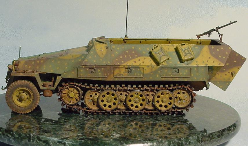
An illustrated guide to tweaking Tamiya's Sd.Kfz. 251 ausf D
|
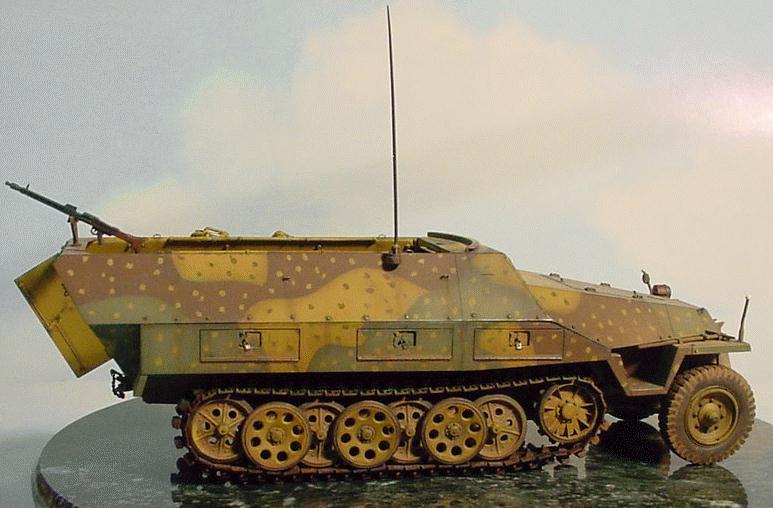
I love tweaks lists. To me, they display an amazing amount of skill & enthusiasm when it comes to making a model just as accurate as possible. For a modeler who is new to the hobby, unfamiliar with a particular vehicle, or not in possession of all the reference material necessary to fully research a particular vehicle, they can be a real treasure. One frustrating aspect to tweaks lists (aside from the cost in dollars, time and sanity to incorporate all of the detail) is that frequently it can be difficult for the writer of the list to describe for the reader exactly what the identified detail looks like, or where it goes exactly, or how it might have been replicated on a model. As a reader, after working my way through a few tweaks lists I thought, "It sure would be handy to see what this is supposed to look like…" and Viola! the idea for an illustrated tweaks list slowly began to seep into my brain. Which vehicle to tweak & illustrate was, of course, the next question. My choice wasn't tremendously difficult. One of my favorite armor vehicles is the ubiquitous Sd.Kfz. 251. Tamiya has several nice kits based on the ausf D chassis, so off I went. For this project I wanted to build something that was close to the basic /1 version so that as much as possible would be generally applicable to other projects. At the same time I’m still a model geek and “stock” is so boring. My choice was made after seeing a picture of a /2 Granatwerfer or Mortar carrier with an ambush paint scheme. How could I resist, one of my favorite vehicles in one of my favorite (and rare on SdKfz 251’s) camouflage styles. Ideally, I suppose, it would have been best for the purposes of this article to take pictures as I went. Unfortunately, I don’t work in a very “linear” fashion when I’m building kits, which leads to some inefficiencies in picture taking if I were photograph as I go. As a result, some of the pictures for this article were taken once the model was completed. Where I knew detail would be hidden or difficult to photograph, once completed, I forced myself to get a few detail shots. Fortunately, being an open topped vehicle, much of the interior detail is still visible once complete. As a result, this article is laid out more in a front – back sequence than the actual construction proceeded. For this project the Eduard PE set was the primary source of aftermarket details. Other PE and resin detail parts, (Part, Royal, Show Modeling, etc.) are available but for this project I used only the Eduard set. Other details were constructed of various bits & pieces, Evergreen and Plastruct plastic strip & rod being the primary materials. Directions "left" & "right" apply, assuming the viewer is looking forward.
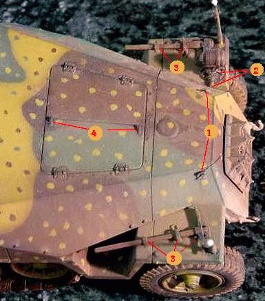
Starting with the forward body then, I added the large tie-downs from the Eduard set to the forward upper sides of the nose where they meet the nose plate (#1). The brackets which support the fender mounted lights are solidly molded to the fender. The bottom of this bracket should either be hollowed out or replaced. I replaced the kit part with a Model Kasten bracket & Bosch light with an MV lens inside (#2). An electrical line also needs to be added to the bracket. This line runs alongside the nose and up into the engine compartment from below. Typical of almost every AFV kit, the clamps that hold tools and equipment on the body or fenders are incomplete due to molding limitations. In this case, PE latches (#3) were added. Another detail that is visible in photographs is the little “Z” shaped latches or handles on the right side access door at the forward and aft leading edge. These were not part of the Eduard set so I bent some up using small pieces of the PE runners (#4).
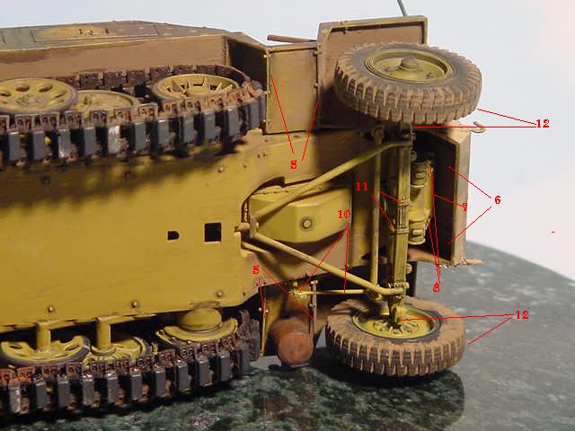
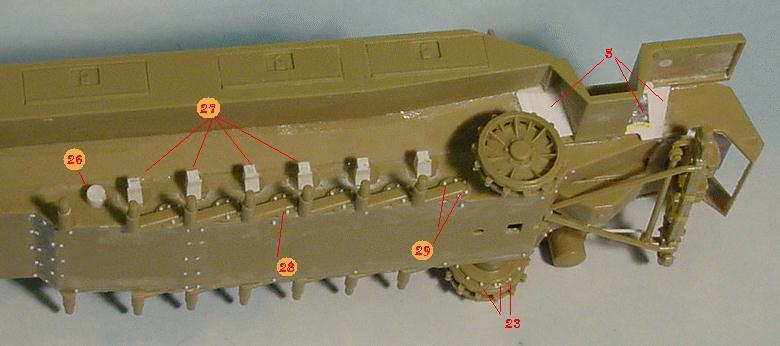
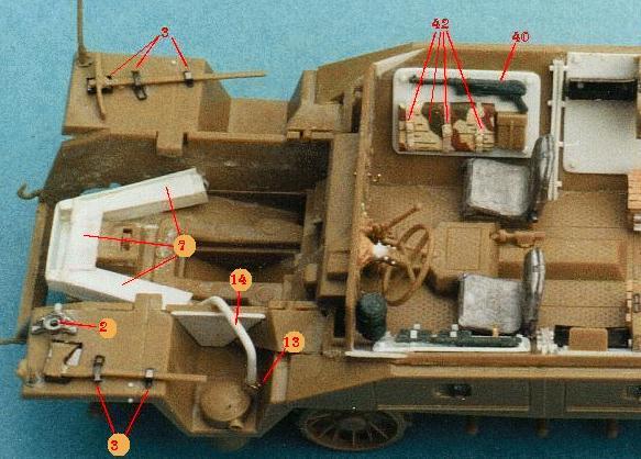
The fenders are held in place by a number of sheet metal pieces and their associated fasteners. These pieces secure the various sections of the fender to each other as well as to the hull of the vehicle. Five thou sheet plastic and strip stock was used along with lead foil replicate the various sheet metal pieces (#5). Lots of filling of ejector pin marks under the fenders is also required to get a smooth look. The backside of the nose plate also needs some attention. Tamiya has molded this area closed but the real vehicle was open to allow air for the radiator to enter. The opening goes aft underneath the nose and tapers to a close as the frame tapers outwards (I think). How far aft this opening goes is speculative so I have made a best guess (#6) Once the air inlet was opened up, the forward portion of the vehicles frame now needed to be replicated (#7). The frame was built up from square sectioned plastic strip with 10 thou brackets and stiffeners (#8). These triangular stiffeners were added below the leading edge of the frame. They do exist on the stock kit but are incomplete once the air inlet is opened up. The frame itself tapers inward as it goes forward.
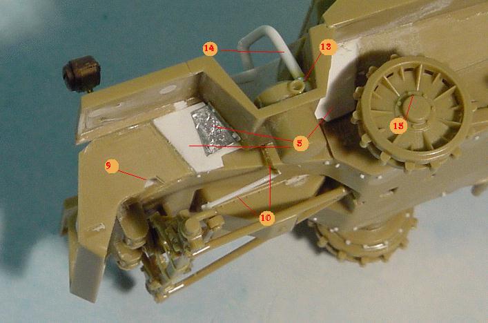
Also, once the back of the nose plate and hull bottom is opened up, the forward hull sides just above the axle, needs to be notched (#9). Presumably these provide clearance for the axle at full axle deflection. With all of the new sheet metal brackets (#5) in place, a two piece steering arm needs to be added. The vertical part of the arm drops down from an opening in the bracket forward of where the fender drops down to support the muffler. The horizontal portion of the arm goes from the bottom of the vertical piece to the LHS wheel pivot (#10). A rather odd feature of the Tamiya kit axle is that it features a rather odd bracket that wraps around the center of the axle, going aft. This bracket should actually be two straps that wrap around the bottom of the axle and go up into the bottom of the hull or frame (#11). One could surmise that when Tamiya measured the vehicle it used as the basis of the kit, these straps were disconnected from the frame and hanging loose on the axle. One thing that can be seen from many pictures is that the front tires toe in slightly at the bottom. (#12). The kit parts are a bit loose and I haven’t figured out how to leave them so that they can rotate and still replicated this toed in look. As such I glue them solidly to maintain the proper angle. Just inboard of where the wheels connect to the axle, there is an “L” shaped lube fitting on the bottom of the axle. I replicated these using 10 thou brass wire. The exhaust system also needed a bit of detailing. Where the exhaust pipe attaches to the muffler, there is a small clamp. I replicated this clamp with a thin piece of the PE runner (#13) much like with the “Z” clamps on the engine hatch. The exhaust pipe itself ends once it goes part way up inside the intake cover. It needs to continue over and down into the engine compartment (#14). If you were to open up the engine hatches to display an engine, this will become very obvious, but even without the engine in place it look odd to see the exhaust system not connected to anything. This picture also shows the road wheels and drive sprockets. The endcaps on the drive sprockets have a small notch/opening on one side (#15). I suspect this is to accommodate a spanner. The road wheel endcaps should have two small notches in them, 180° apart (#16). These were made using a very new (sharp) Xacto blade. Moving back along the outside of the main hull, a number of other items needed to be added or redone.
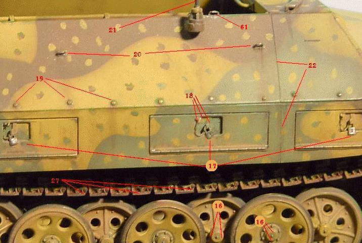
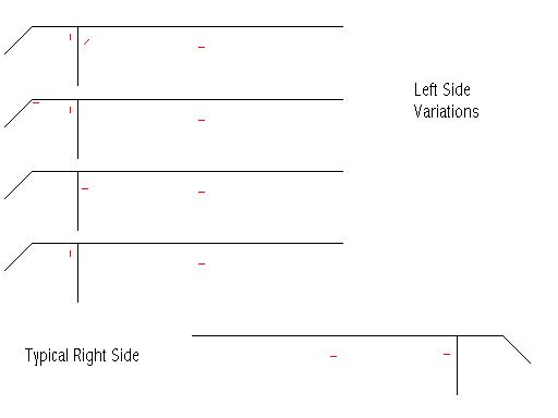
The locks for the stowage boxes are too small and mounted too high in the indentation. I added a 0.5mm wide strip that runs from the top of the indentation to the halfway point and then another that protrudes outward. The lock is attached to that. There should also be a small loop at the upper aft corner of the indentation with a chain attached (#18). Once the brackets/strips were added, the padlock from the Eduard set were added in their correct location (#17) In my opinion, the bolt detail along the side is a bit understated. I sanded off the old bolt heads and new bolt heads were added (#19) using Plastruct hex strip stock. I also added tie downs at appropriate locations along the upper hull (#20). The tie downs were created by glueing a X x X piece of strip stock to the kit surface and then 5 thou wire was used to make the tie down itself. Tie down layouts vary from vehicle to vehicle. I can't determine if these configurations are unique to specific manufacturers or if there is some other explanation. The variations occur primarily on the left side. I have only seen two pictures showing right side tie downs that vary from the "standard" pattern. Below is an illustration of the left side variations and the "standard" right side seen in photos.
I added an antenna and it’s associated wiring as well (#21). The antenna was made from 20 thou rod that has been scraped with an Exacto knife and then sanded to attain the proper taper. Also, the kit shows a raised weld seam where the cab & hull are joined. In reality there should be a slight gap or panel line at this line. The join line was sanded off & rescribed (#22).
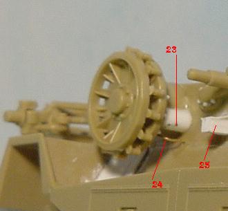
The Drive Sprocket housing needs a smaller secondary housing added to the aft side and bolt detail added to the back of the sprocket (#23). A hydraulic (or pneumatic) line was added the hull to the drive sprocket housing (#24). This line exits the hull above & behind the secondary housing and enters it along the upper surface. Torsion bar stops or bumpers were also added above each torsion bar (#25 & #27). These are on all ausfs of the Sd Kfz 251 as well as the parent Sd Kfz 11 and are completely missing from the kit. When I built this kit was I had to make each of the bumpers from scratch. Since then, AFV Club has released its upgrade for the SdKfz 251, which includes very nice injection molded, parts as well as most everything below the fender/cargo boxes.
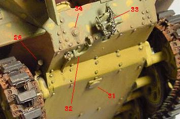
I added a track tensioning mechanism to each side above last wheel on either track run (#26). This consisted of an anchor post (sticking out from the hull, forward of the last torsion bars), a tensioning bracket added to the top of the last torsion arm and a tensioning screw with a bolt head that goes from the anchor to the bracket and then protrudes out the back. The kit tracks are somewhat undersized, a bit featureless and they just can't replicate that characteristic sag. I replaced them with Anvil tracks which are fantastic but, unfortunately, no longer available. Other replacement track sets are available from Fruilmodel and Model Kasten. At this point I must admit to being able to talk the tweak talk, but couldn't quite walk the tweak walk. The Sd.Kfz. 251's and parent Sd.Kfz. 11's torsion bars/torsion arms protrude about 1 mm beyond the torsion arm bearing on the lower hull (#28). The road wheels on the real vehicle do not stick out further, the difference is taken up by shorter axles. The Tamiya kit has these molded directly on the hull side. MR and AFV Club make individual replacement torsion bars, the AFV set being the more complete. Each of the torsion bar bearing covers should have 6 bolt heads securing them (#29). If you do not separate the torsion arms then only 5 are necessary, as the sixth cannot be seen. Much of what was done by hand in the section has been rendered completely unnecessary with the release of the AFV Club suspension set for the 251 (AF 35043). This set pretty much takes care of everything below the stowage boxes… but of course it wasn't available for this build.
I added more bolts to the underside of the hull (#30). Bolts locations can be confirmed photographically to line “X”. Forward of that is speculation; I just took my best guess at a layout. I also added a small access plate forward of the aft hull break (#31). This can be seen in many photographs. The air valve and it’s associated piping, which connects the valve to the aft pneumatic air inlet port (#32) was also added.
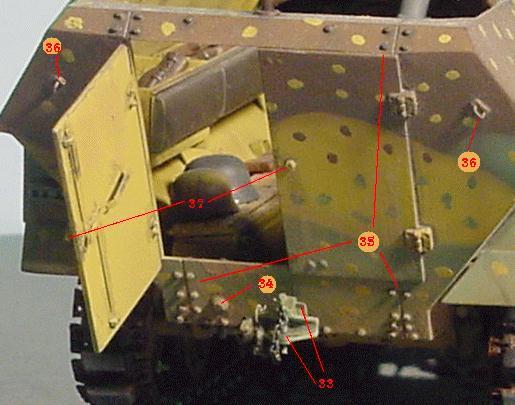
The kit tow fitting is very simplified compared to the real one. Various details, such as adjustment handles & a chain need to be added (#33). I added the electrical connector port to the left side (#34). This was made from stacked 10 thou plastic discs that were punched out using a Waldron punch & die set. Again, the bolt detail on the kit is a bit understated (to my view) so I sanded it off and new bolt head detail was added (#35) using the hex strip stock. Tie downs were added to the upper corners (#36) using the same method as with (#20). The Tamiya kit has handles on both back doors. In reality, there should be a handle on only the left door; the right door has a bolt head where the handle would be. The handle on the left door was upgraded (#37) using 10 thou bras rod and a short strip of plastic.
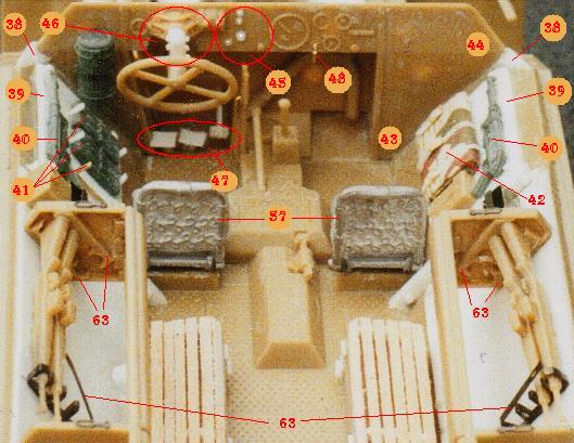
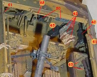
INTERIOR In the shot below you can see the number tags (#43) and (#44) which appear to be attached to nothing in particular. (#43) is where the transformer for radio was added to right side below armor plate. It can be seen in the subsequent picture. (#44) is where the speaker for the radio needs to be added. I missed this detail during the construction of this model and it wasn’t until I shared some pictures of the completed kit with Detlev Terlisten that he pointed out it was missing.
A couple of different dashboard configurations can be seen in various pictures. I cannot tell from the photos if these are manufacturer specific or ausf specific. I have chosen the one that I have seen most often in pictures. I added indicator lamps and an ignition to the dashboard (#45). The steering column is very under detailed compared to the real vehicle. There is a complex bracket and lots of bolt heads that secure the steering column to the dash. Coincidentally, this bracket looks very similar to the Bosch light bracket that was replaced earlier. I detailed it with a few bolts (#46) and added it to the dash.
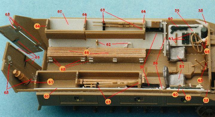
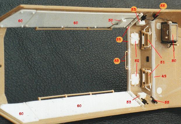
Transitioning to the interior of the upper hull, There is a step where the front visor plate meets the back end of the top hood (bonnet?) plate. A 10 thou strip added (#49) to this join and then sanded smooth to eliminate the step. Various details from the Eduard se as well as some scratch built details (#50) were added to radio. A headset, headset connector cable and antenna cable were added as well. The front armored glass windows were detailed with latches, forehead rests & bolt detail (#51). One of these days, it might be interesting to recast this part in clear resin and paint all but the glass portion, but unfortunately not this time around. Above the driver & radio operator there are head cushions. I could definitely see where these would be necessary especially driving over rough terrain. I added the brackets using 10 thou brass wire, bolts from hex strip, straps from Tamiya tape and the head protection pads themselves were made from 10 thou sheet plastic (#52). On the sides of the cab I added armored glass side window blocks (#53) from strip stock. These were clear glass on the real vehicle so clear strip stock (if you can find it) or clear resin block should be used. I painted them silver and then over coated the silver with a thin film of Tamiya Clear Green to simulate the glass. Over the glass blocks I added the armored side window brackets (#54) (brackets not installed at time of photo) from the Eduard set. PE brackets for spare armored glass blocks added just below the side windows (#55) Both the cab and the fighting compartment had a flange that was used to bolt the forward and aft sections of the hull together. (#56) Shows the lower half of the flange and (#59) shows the upper part of the flange. Most PE sets only provide one piece for this flange. I replicated the front & aft sections using 10 strip stock with added bolt detail as well. This flange runs up both sides of the cab and fighting compartment. Only the cab side has the flange across the top. In most pictures I have seen there appears to be a bit of a gap between the forward and aft flanges. This was replicated by using a very small piece of strip stock to set the gap. A grab handle, base plate & bolt details were added to the top flange (#58). The seats in the Tamiya kit do not look like the majority of seats I have seen in photos. I added more representative driver & RO seats from MR (#57). I added the upper & lower hull armor liner pieces (#60) out of 10 thou sheet plastic and added bolt detail to secure the armor. The spacing and number of bolts varies in the few pictures I have seen that show the bolt detail clearly. I used the spacing from one picture but other patterns can be seen. Care must be taken when gluing the armored liners to the hull sides. In one instance I used too much glue in one spot, which was sufficient to cause a sink mark in the armored liner. On another kit, some warpage in the upper hull resulted. The Eduard PE set supplied the tie downs wich are located along the top of the hull (#61). The tie downs are sandwiched between hull exterior & armor liners at the front and back of the hull opening. I also added brackets to support the de-mounted machine guns to lower armor liners (#62). This consists of a rest piece and a clamp piece. The endplates and brackets for crew rifles (located behind the forward backrests need a bit of work (#63) The barrel end clamps are part of the Eduard set, the buttplate ends are made from modified kit supplied brackets. These look more like what I see in photos than what is supplied in the PE set. More Eduard clamps were added (#64) to the tops of the backrest supports. The seats in the fighting compartment were also equipment lockers of a sort and they were double hinged so that different layers could be accessed independently. This means that two sets of hinges are required (#65), an upper and lower set. Both sets are made from thin strips of 5 thou plastic with a 20 thou rod for the hinge. I glue a long section of rod to the strip and then slice off the appropriate lengths for the hinge. Most ausf Ds utilized wooden benches rather than the leather-covered seats supplied in the kit. The leather covered cushions were actually more correct for an ausf C. The wooden battens of the ausf D's seats were attached to endplates which formed the shape of the seat. For some reason, the shape of the seat contour varies in the photos I have seen. I don't know what the rationale for this variance is, possibly just manufacturer preference. I have simply chosen one version. Thin wood strips and endplates (#66)were added to the top of the kit seat bases. Returning to the Eduard PE set a new Fire Extinguisher bracket (#67) was added. The rear doors are a bit featureless and so a few items were added to dress them up. Grandt Line bolts (#68) were added to inside of door hinges on the door and hull backplate as well as the interior door handles, actuation rods & springs (#69) to detail the door latch mechanism. The last items added to the interior were the holders for spare armored glass blocks (#70). Locations vary so check your reference material. There is one last item that I would like to address that wasn't part of this model, but would be a part of most SdKfz 251 models. The shield that protects the forward gunner is an item that is routinely provided as a PE item, presumably to replicate its thickness to scale. In reality, this shield was a fairly thick piece of armor plate and the kit shield is actually very close in scale. If some enhancement was to be done to this piece, the most effective thing to do would be to use very rough sandpaper (or a motor tool bit) to replicate the rough cut edges of the shield. And that's about it for the basic kit. To build the mortar carrying vehicle, I added the mortar from another Tamiya kit, (#35193). The base plate was added to the nose of vehicle using very thin wire. Factory converted 251/2's have a small ridge which supports the mortar base when it's stowed in the vehicle. In keeping with the unique paint scheme, I decided to model this vehicle as a field conversion, so the base was not added.
Bits & Pieces Wherever bolt heads were added they were made from hex shaped strip that was cut to length (thickness) using "The Chopper". Two sizes of hex strip were used, .5 mm and .7 mm. Protruding bolts with nuts were added using the Grandt line of details. Paint & Weathering. As I mentioned in the intro, my kit is based on a photo of a 251/2 Granatwerfer that has been discussed from time to time here on Missing Links. The hard edged "ambush" scheme was created using paper masks over the Panzer Yellow base. Several attempts were made to match the paint scheme in the photograph as closely as possible. Some attempts resulted in color combinations that just didn’t work, some had to be redone because I put the masks in the wrong location. In each case the paintwork was sanded back to the bare plastic and I started all over again. Predictably, the right side, for which I had no reference material, was a bit easier to paint, but not totally. I made several drawings of different paint scheme layouts, trying to match the balance or “feel” of the scheme that is visible on the left side. This wasn’t quite as easy as I suspected it might be but at least I didn’t have to worry about matching a photo. My standard reference for painting German armor is James Blackwell's "Painting Panzers" article in the "Articles" section here on Missing Links. I also found Jari Lievonen's "Painting Models - Evolution or Revolution" to be very helpful for this project, in particular, "Case 2". Once the basic scheme is laid out, each color panel is drybrushed to vary the color, intensity and reflectivity of the paint. This breaks up the uniformity of the finish and provides a more realistic appearance. The tracks were painted a metallic dark gray and then several coats of Rustall were painted on to give it that "well used" look. The final weathering touch was to add pastel "dust" under the fenders, on the wheels & tracks and up the sides of the hull. And that's about it. This was my "one year" project, i.e. I started it one year after I started building armor models. I wanted to test my detailing skills and see if I could incorporate all the things I had learned about the real SdKfz 251 into a kit. This project took me 4 months to complete. Since then I have built a couple of other 251's and they haven't taken quite as long. I'd like to thank Detlev Terlisten and Piet Van Hees for their expertise and encouragement during this project. My results would have been much diminished without your help, gentlemen. References: Books Schutzenpanzer Ryton Publications By Bruce Culver & Uwe Feist 1996 Nuts & Bolts vol. 6, Kanonenwagen (Sd.Kfz. 251/9) Nuts & Bolts By Detlev Terlisten 1997 The Sd.Kfz. 251 Half-Track, Osprey Vanguard 32 Osprey Publishing Bruce Culver 1983 Sd.Kfz. 251 Half-Track, New Vanguard 25 Osprey Military Bruce Culver 1998 Sd Kfz 251 in Polish Museums, Militaria in detail #1 Wydawnictwo Militaria By Janusz Ledwoch 2000 Sd.Kfz. 251 in Action, Armor Series No. 21 Squadron/Signal By Charles Climent 1981 Web Pages/Magazines Hanomag Sd.Kfz. 251 http://www.geocities.com/MotorCity/Pit/3515/251/index.htm Webmaster, Piet Van Hees AFV Interiors website German Sd.Kfz. 251 Semi-track Part 1 http://www.kithobbyist.com/AFVInteriors/251/251a.html German Sd.Kfz. 251 Semi-track Part 2 http://www.kithobbyist.com/AFVInteriors/251/251b.html Webmaster, Mike Kendall |
|
|